Bently Nevada 3500 Protection Logic: Confirming Sensor State vs. Assumed State
The trip happened. The operator screen tells you a story. The 3500 history buffer tells you what actually fired - and they're not always the same.
- 1.Key takeaways
- 2.Why the 3500 still matters in 2026
- 3.The protection chain — what's actually in the rack
- 4.The 3500/42M — where the threshold lives
- 5.Voted logic — what was decided at design time
- 6.The DCS handshake gap — why alarm logs mislead
- 7.Proximitor calibration — the silent failure mode
- 8.The walkdown that works
- 9.The cross-discipline closer
Key takeaways
- The 3500/42M Proximitor module is where the trip threshold lives and where the trip relay fires. Not the DCS, not the operator screen, not the alarm log. If you don't know what the 42M is doing, you don't know what tripped the machine.
- The trip fires before the alarm log catches up. There's a 200–500 ms gap between the relay firing and the DCS time-stamping the event. Reading the alarm log to figure out cause means reading the symptom, not the source.
- Voted logic (1oo2, 2oo3) was selected at design time for a specific risk tradeoff. It's not something to second-guess at 3 AM during a post-trip walkdown.
- Proximitor calibration is the silent failure mode. The 42M reads voltage from probe gap; calibration drift means false mils readings, which means false confidence in a trip threshold that's no longer where you think it is.
- The walkdown that works: pull the 3500 channel-level history buffer, identify the channel that hit threshold first, walk back to the physical bearing, inspect probe gap and shaft surface. Symptom-first walkdowns from the alarm log will lead you wrong about half the time.
Why the 3500 still matters in 2026
The Bently Nevada 3500 protection rack is the standard architecture for vibration protection on critical machines — large steam and gas turbines, centrifugal compressors, big motors and generators. The rack has been in continuous production since 1995 in roughly its current architecture, and the installed base across refineries, chemical plants, LNG facilities, and power stations is staggering.
The replacements that have emerged — System 1 Evolution, the newer Bently Nevada Orbit platform, GE's Cassia, third-party machine protection systems from Vibro-Meter and Rockwell — all coexist with installed 3500 racks rather than replacing them. A plant builds a new train and specs a 3500 because that's what the I&C tech knows. A plant retrofits an old train and keeps the 3500 because pulling and re-cabling the rack is its own outage scope.
If you work rotating equipment in 2026, you work on machines with 3500 protection. The skill of walking a 3500 trip back to a physical bearing is one of the most valuable cross-discipline skills in the field.
The protection chain — what's actually in the rack
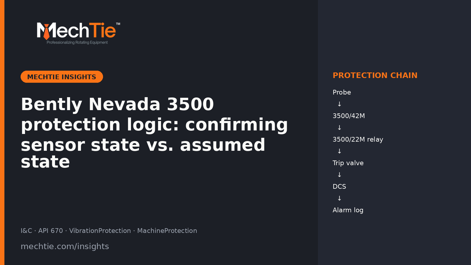
A vibration protection trip on a centrifugal compressor or turbine moves through this chain:
Proximity probe → extension cable → 3500/42M Proximitor module → 3500/22M relay module → DCS handshake → operator screen → plant alarm log.
Each link in that chain does a specific job, and each link can be the source of a mistaken diagnosis if you don't know how it behaves.
The proximity probe is a small inductive sensor mounted in a bearing housing, looking at the shaft. It generates a voltage proportional to the gap between probe tip and shaft surface, in the range of 200 mV/mil. Two probes per bearing in an X-Y configuration give you orbital data. An additional axial probe gives you thrust position.
The 3500/42M Proximitor module sits in the rack, accepts the probe voltage, and converts it into engineering units — mils peak-to-peak for radial vibration, mils for axial thrust. The 42M is also where the trip threshold is configured. Typical thresholds for radial vibration: alert at 2.5–4 mils peak-to-peak, danger (trip) at 4–8 mils peak-to-peak depending on machine class and OEM spec.
The 3500/22M relay module takes the trip command from the 42M and drives a relay contact that's wired into the trip system. The relay fires the trip valve, which dumps oil from the trip header, which shuts down the machine.
The DCS handshake is the soft side. The 3500 sends an event packet to the DCS via the system gateway (typically TCP/IP for newer installations, RS-485 for older ones). The DCS time-stamps the event and writes it to the alarm log, which the operator sees.
The 3500/42M — where the threshold lives
The single most common diagnostic mistake during a post-trip walkdown is treating the operator screen or the DCS alarm log as the source of truth. They aren't. They are the downstream view of an event that happened in the 3500 rack 200–500 ms earlier.
The 42M module is where the live signal is compared against the trip threshold. The 42M fires the relay. The relay shuts down the machine. By the time the operator screen reports "HIGH VIBRATION TRIP," the machine is already coasting.
For the walkdown, this means: don't reverse-engineer cause from the operator alarm log. Pull the 3500 history buffer directly. Every channel in a 3500 rack has a channel-level event history — a high-resolution record of pre-trip, trip, and post-trip data, time-stamped to the rack's own clock. That's the source of truth.
The history buffer also captures which channel hit threshold first — the one that actually tripped the machine — versus channels that exceeded threshold afterward because the machine was coming down through a critical speed or a resonance. A walkdown that starts from "the alarm log says channel 4 was over threshold" will lead you to the wrong bearing if channel 4 was actually a downstream consequence of channel 7 tripping first.
Voted logic — what was decided at design time
Most 3500-protected machines run voted logic on radial vibration channels. The two common configurations:
1-out-of-2 (1oo2): Either probe in the X-Y pair tripping causes a machine trip. Faster — the machine comes down on the first signal that crosses threshold. Vulnerable to nuisance trips on a single faulty probe.
2-out-of-3 (2oo3): Three probes per bearing; two must exceed threshold to trip. Slower — the machine has to be in actual trouble on two probes before tripping. Tolerates a single faulty probe.
The voting configuration was decided at design time by the OEM and the EPC, usually documented in the machine's protection P&ID and the 3500 configuration software. It's a deliberate risk tradeoff — production availability vs. machine protection.
You don't change voted logic during a post-trip walkdown. If a 2oo3-voted machine tripped, two of three probes exceeded threshold. If a 1oo2-voted machine tripped, one probe was enough. Walking the inspection without knowing the voting configuration is a common error.
The DCS handshake gap — why alarm logs mislead
The 200–500 ms gap between the 3500 firing the trip and the DCS time-stamping the event sounds small. It isn't, for a machine that's spinning at 12,000 RPM. In that window, the rotor has made 25–100 revolutions, each one capable of triggering additional vibration channels as the machine coasts through resonances or shifts axial position.
Operators and DCS log viewers see all of these downstream events in roughly chronological order. The temptation is to read them top-to-bottom and infer cause from the time stamps. The result: the actual root-cause channel is hidden among the consequences.
The fix is to read the 3500's own time base, not the DCS time base. Every channel in the rack is time-stamped against the rack's clock, with millisecond resolution. The channel that hit threshold first in rack time is the trip source. Everything after it in rack time is consequence.
For centrifugal compressor surge events and recip cylinder unloader interactions, this same discipline applies — confirm sensor state from the source, not from the downstream view.
Proximitor calibration — the silent failure mode
A 3500/42M reads voltage from the proximitor probe gap. If the proximitor was last calibrated to a thicker shaft material or at a different gap, or if calibration has drifted from age and temperature, the live mils reading is off by a known multiplier.
The 42M doesn't know it's miscalibrated. It applies the configured volts-per-mil scale factor and reports an engineering-unit number. The number looks right. The trip threshold is the wrong threshold.
In the field, proximitor calibration drift is the failure mode that goes unrecognized longest because the symptoms look like other problems. A machine that's vibrating fine according to the rack but showing rising suction temperatures or galloping flow — same field signs we discussed in the centrifugal compressor surge piece — might actually be approaching surge with a fouled probe reading low mils.
Check the calibration record before you trust the trip threshold. Bently's recommended interval is annual; many plants stretch it to outage-aligned (3-6 years). Stretched intervals are where the silent drift accumulates.
The walkdown that works
- Pull the 3500 history buffer for every channel on the affected machine. Don't start with the alarm log; start with the rack-level record.
- Identify the channel that hit threshold first in rack time. That's the actual trip source.
- Confirm the voted-logic configuration for that channel. 1oo2 means the channel tripped alone; 2oo3 means another channel hit threshold within the voting window.
- Walk back to the physical bearing or thrust collar that the channel monitors. This is where the work happens.
- Inspect the probe gap, the shaft surface under the probe, and the probe cable. Common findings: scaled shaft surface giving false-high mils, loose probe mount producing 1× run-frequency signal, cable damage producing spurious signals.
- Pull the calibration record for the proximitor. If it's been stretched past the recommended interval, the trip threshold isn't where you think.
The diagnostic skill that pays in this work — and we made the same point in the recip valve diagnostic piece — is reading the actual sensor state, not the assumed state.
The cross-discipline closer
If you work rotating equipment on machines with 3500 protection, this walkdown is the bridge between mechanical and I&C. The mechanic who can pull a 3500 history buffer and identify the trip source is the mechanic who gets called first for the next post-trip inspection. The I&C tech who understands what the mechanic is going to find at the bearing — and can confirm whether the cable, probe, or proximitor is the problem — is the tech who completes the diagnosis on the same shift.
That's the cross-trade specialist plants pay for in 2026.
Are you an I&C specialist or rotating equipment mechanic with 3500 experience? Build your verified MechTie profile — list the specific 3500 modules you've worked on (42M, 22M, 25, 33, 40M, 44M), the OEMs whose machines you've protected (Solar, Siemens, GE Vernova, Dresser-Rand, Elliott, MAN Energy Solutions), and your API 670 commissioning or troubleshooting experience. Plants searching for post-trip walkdown specialists find your name first.